| |
| |
Mastering
3D Studio MAX R3 |
Setting Up for Surface Tools Work
Now we will make our reference copy so that we can apply a surface and
see what’s happening with our model as we work. Since we are only
going to create half the model and then mirror it, we’ll delete the
unnecessary segments first. We’ll also check that our viewport settings
are optimal for working in Surface Tools.
- 1. Select the spline cage, click the Edit Stack
button, choose Collapse All, click Yes and then OK.

| 2. Click the Segment
Sub-Object button.
|
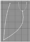
- 3. Select all the segments on the top half of the
top viewport, as shown in Figure 5.20.
FIGURE
5.20 Select half the segments of the spline
cage for deletion.
- 4. Delete these segments. When we are done modeling
half our narwhale, we will mirror it and weld the halves together. Click
the Sub-Object button to get out of sub-object mode.
- 5. Select the cage in the front viewport and Shift-drag
it upwards. Choose Reference from the dialog box. Move the reference
copy up in the top view so it does not obstruct your view of the original.
- 6. Apply a Surface modifier to the reference copy.
- 7. In the Modify tab of the Surface modifier, check
Remove Interior Patches. If you can’t see the surface in the perspective
viewport (meaning the normals are pointing away from you when they should
be facing you), check Flip Normals as well.

| TIP Small changes
(fusing vertices, creating a new line) in the spline cage can result
in the surface being reversed. Try flipping normals if the surface
seems to be inside out or invisible.
|
- 8. Right-click the spline cage, select Properties,
and check Vertex Ticks. Make sure your 3D Snap settings are set to Vertex
and not Grid Points, and Use Axis Constraints is unchecked. Keep 3D
Snap off for now.
- 9. With the spline cage still selected, click the
Vertex sub-object button and turn the weld threshold to zero by right-clicking
the spinner next to Weld.
|
|
|
|
| TIP You can
reset many spinners in MAX by right-clicking either of the spinner
arrows. (Usually, the spinner will be set to zero; sometimes the interface
designer has it reset to its default value.) Right-clicking while
you’re dragging a spinner arrow sets it back to the last value.
|
- 10. Name your spline cage “narwhale spline
cage” and your surfaced reference “narwhale surface.”
Creating the Tail
Now your model should be a long, tapered body. You should have a surface
on one version of a model that references the spline cage version. We’re
going to add the flukes of the tail by drawing a spline that describes
the shape of the tail (from the top) and then connect this spline to the
vertices of our spline cage with new lines. First, let’s simplify
our view so that we can only see the very last cross-section of our spline
cage, where we are going to add the tail.
|
|
|

| NOTE If you
want to start from here, you can open the file ST_narwhale_2.max
on the CD.
|
- 1. Select the spline cage, click the Vertex Sub-Object
button, select all the vertices to the right of the leftmost circle
(as shown in Figure 5.21), and then click Hide.
FIGURE
5.21 Hide these vertices.
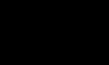
- 2. With 3D Snap off, click the Create Line button
and, in the top viewport, draw the spline shown in Figure 5.22. Since
we’ve hidden the rest of the model, you will only see the inset
area of the graphic in your viewport; the figure gives you a reminder
of what you are looking at in the model.
FIGURE
5.22 Spline to draw, superimposed on hidden
model
- 3. Click the Spline Sub-Object button, select the
new spline in the front viewport, and move it down so the endpoint aligns
with the middle vertex of the end of the cross-section.
- 4. Click the Vertex Sub-Object button, marquee-select
the connecting vertices, circled above, and click Fuse.
- 5. In the top viewport, right-click the new vertices
of the tail, choose Bezier Corner, and shape them as shown below.
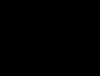
- 6. With 3D Snap on (set to Vertex Only), click the
Create Line button and connect the vertex at the top of the base of
the tail to the last vertex of our tail spline (Figure 5.23). Right-click
to end the line. Click the Create Line button again to turn it off.
You should see a new piece added to your reference surface, as shown
in Figure 5.23. If you don’t, try Fusing the vertices you just
created.
FIGURE
5.23 The newly created line (left) and a new
piece of reference surface due to this line (right)
|
|
|
|
| NOTE If you
can’t see your surface, remember to try the ideas in the troubleshooting
section earlier in this chapter, such as adjusting the Surface threshold
on the reference surface.
|
- 7. With 3D Snap off, select vertices, change their
tangency, and shape the new points in the tail. Remember to marquee-select
when moving a point.
|
|
|
|
| TIP If you have
Area Selection checked and all your coincident vertices selected,
you can click the Cycle button to cycle through the coincident vertices
and shape the one you want. If Area Selection is unchecked, you will
cycle through all the vertices of the spline (including the hidden
vertices).
|
- 8. Go to the Spline sub-object level, select the
tail spline, and copy the spline by Shift-dragging it slightly downwards
in the front viewport.
- 9. Go to the Vertex sub-object level, click the
Refine button, and add a vertex to the back circle, near the end vertex
of the spline you just created. Click the Refine button again to turn
it off.
- 10. Select the vertex you just created and the nearby
end vertex and then click Fuse.
- 11. With 3D Snap on, create another line connecting
the vertex at the bottom of the base of the tail to the vertex at the
end of the tail; right-click to end the line. Turn off 3D Snap.
- 12. Select the two vertices at the tip of the fin
and click Fuse. Select the vertices at the very end of the narwhale
body and click Fuse.
- 13. Click Unhide All.
|
|
|
|
| NOTE If you
want to start from here, you can open the file ST_narwhale_3.max
on the CD.
|
- 14. With 3D Snap on, zoom in and rotate your view
so you can create a line between the two vertices shown in Figure 5.24.
When you are done, turn off 3D Snap. You may need to fuse the vertices
afterward. If you still don’t have your surface, go to the object
level, select your surface reference object, and check or uncheck Flip
Normals.
- 15. Change tangent types and maneuver vertices and
Bezier handles to shape the tail fin and round out the rest of the cage
as shown from two angles in Figure 5.25. You will need to roll your
view and zoom in and out as appropriate. When you want a smoother curve,
choose Smooth or Bezier tangent type; when you want a precise change
in curvature, choose Bezier Corner.
FIGURE
5.24 Create a line between these two vertices.
|
|
|
|
| TIP Remember
to use the W key to maximize or minimize a viewport.
|
© 2000, Frol (selection,
edition, publication)
|
|
)
)
)
)
)
)
)
)
)
)
)