| |
| |
Mastering
3D Studio MAX R3 |
Using Reference Images
Although we won’t be using them for actual modeling in this chapter,
let’s take a quick look at how to work with reference images. One
option is to create three planes and map each with an orthogonal reference
image in the diffuse channel. Another option is to put a different reference
image in the background of each viewport. Let’s do the latter.
- 1. Reset MAX.
- 2. Choose Views Ø
Viewport Background to bring up the dialog box in Figure 5.1.
- 3. Select Front in the Viewport drop-down list.
- 4. Click the Files button.
- 5. Choose \Maps\Backgrounds\House.jpg
and click Open.
- 6. Under Aspect Ratio, check Match Bitmap.
- 7. Check Display Background, Lock Zoom/Pan, and
Active Only.
- 8. Click OK to close the dialog box. Your front
viewport now has the house image in the background. You can zoom in
to the photo as necessary this way.
- 9. Repeat steps 3 through 8, loading reference images
into the top and left viewports for modeling.
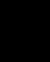
FIGURE
5.1 The Viewport Background dialog box
Understanding Splines
In Chapter 4, we used splines in different compound objects. Patch and
NURBS modeling are spline-based systems, so we need to discuss splines
in more depth.
The term spline originated in ship-building, where a piece of
wood would be shaped into a curve by distorting it with two pegs. Mathematicians
borrowed the word to describe curves in terms of mathematical functions.
In computer graphics, a spline is a curve defined by mathematical functions
rather than a straight line segment defined solely by its two vertices.
Bezier Splines
We have a mathematician named Pierre Bézier to thank for the math
behind patch surfaces as well as the splines created with the Shape tools
in MAX. Bezier splines are also fundamental to vector drawing programs
like Illustrator, FreeHand, and CorelDraw, as well as to the Pen tool
in Photoshop. You need to understand them if you are going to work with
computer graphics.
Editing a Bezier Spline
The vertices of an editable spline in MAX have four options for interpolating
the tangents of the curve between them: Smooth, Corner, Bezier, and Bezier
Corner. Let’s look at what these do to a spline.
- 1. Reset MAX.
- 2. Drag out a circle in the front viewport (Create
Ø Shapes Ø
Circle).

| 3. Go to the Modify tab,
click the Edit Stack button, and select Convert to Editable Spline
from the drop-down menu.
|

- 4. Click the Sub-Object button and stay at the Vertex
level.
- 5. In the front viewport, drag a marquee around
the whole circle to select all its vertices. You should see four vertices
with handles, as shown in Figure 5.2. These are the default Bezier tangents.
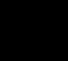
FIGURE
5.2 Vertices with Bezier handles
- 6. Select just the top vertex and move one of its
handles. Notice that the handles on either side of the vertex are dependent,
and therefore always move together.
- 7. Right-click the vertex on the right side of the
circle. In the shortcut menu you will see the four vertex options, with
Bezier checked. Select Smooth from the menu. The handles disappear,
and you have a smooth curve through the point determined entirely by
MAX.

- 8. Right-click the vertex on the bottom of the circle
and choose Corner from the shortcut menu. This changes the tangents
to straight lines coming in and out of the point.
- 9. Right-click the vertex on the left side of the
circle and choose Bezier Corner from the shortcut menu. This gives you
handles that look exactly like those we saw with Bezier.
- 10. Move one of the tangent handles. This time the
handles are independent, so you can shape the curve more precisely.
Your circle should look something like Figure 5.3 when you are finished.
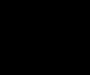
FIGURE
5.3 Circle with tangents edited
Non-Uniform Rational B-Splines (NURBS)
B-spline is short for basis-spline, a mathematical concept including
Bezier splines and NURBS, the two types of splines available in MAX. A
rational B-spline is one that is defined mathematically as the ratio of
two polynomial functions. A non-uniform B-spline is one in which the influence
of a curvature can be varied. A non-uniform rational B-spline is
called NURBS for short. Fortunately for those of us who don’t breathe
the rarefied air of higher mathematics, we never have to understand any
of the math to use NURBS.
|
|
|

| NOTE Another
type of spline, called H-spline for “hierarchical spline,”
is available through a plug-in for MAX called Rodin from Digimation.
|
With NURBS, the curve of a surface is shaped by control vertices (CVs)
that do not lie on the NURBS curve. (This is true even of point curves,
except in this case, the CVs are not accessible and points on the curve
are accessible, in order to provide an alternate interface for modeling.
Point curves and surfaces can be converted to their underlying CV form.)
Each CV has a weight which determines the extent of its influence over
the curve.
Shaping a NURBS Curve
Let’s look at how CVs shape a NURBS curve.
- 1. Reset MAX.
- 2. Choose Create Ø
Shapes Ø NURBS Curves.
- 3. Click the CV Curve button.
- 4. In the front viewport, click once to create one
endpoint, click in another place to create a CV, click in a third place
to create the other endpoint, and then right-click to end the curve.
Your curve should look something like Figure 5.4.
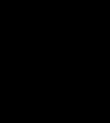
FIGURE
5.4 NURBS curve with control vertex
- 5. Go to the Modify tab and click the Sub-Object
button to get back to the Curve CV level.
- 6. Select the CV that is shaping the middle of the
curve.
- 7. In the CV section of the Modify tab, change the
weight to 5. Notice how the CV pulls the curve towards itself more strongly,
as in Figure 5.5.
FIGURE
5.5 The weight of the CV has been increased
here.
- 8. Refine the curve with another CV by clicking
the Refine button and clicking the curve. Click the Refine button again
to turn it off.
- 9. Move the new CV around to change the shape of
the curve, as in Figure 5.6. Notice that if you move it so it is coincident
with the first CV, you get a sharp edge.
|
|
|

| TIP Making two
or three CVs coincident gives you sharper edges in NURBS.
|
FIGURE
5.6 Shaping the NURBS curve with a new CV
Modeling with Patches
A Bezier patch is a surface defined by vertices and the tangents of the
edges between the vertices. A patch can have either three sides (Tri patches)
or four sides (Quad patches). Quad patches tend to be preferred when modeling
smooth surfaces, except when a Tri patch is necessary (to fill a hole
in a model) or when it is helpful for modeling a particular detail. The
vertices of patches can be coplanar (giving you Bezier handles that move
together across the vertex) or corner (with independent handles).
MAX gives you several ways to model in patches. The traditional way is
to start with a patch, subdivide it, add patches, and adjust their curvature.
In MAX, primitives, meshes, and loft objects can also be converted to
patches and then edited in patch form. Patch modeling has recently enjoyed
a rennaisance with MAX users due to the addition of MAX Surface Tools
as an additional method of modeling in patches.
Building and
Editing Patch Surfaces
The old method of working with patches has been called “knitting
a house.” The advantage of learning this way of modeling is that
it applies to most 3D applications, so you will be able to transfer your
skills easily to a job that requires you to model in patches in a different
program. The disadvantage is it requires a great deal of patience and
practice, but that’s true of most things in 3D.
Creating Patches
Let’s start by creating a patch and subdividing it.
- 1. Reset MAX.
- 2. Select Patch Grids from the Create drop-down
menu (Create Ø Geometry Ø
Patch Grids).
- 3. Click the Quad Patch button and drag out a patch
in the top viewport.
- 4. Go to Modify Ø
Edit Stack and choose Convert to Editable Patch from the drop-down menu.
|
|
|
|
| NOTE You can
also use the Edit Patch modifier, analogous to the Edit Mesh modifier
for meshes.
|

| 5. In the Selection
rollout, click the Patch Sub-Object button and then select the patch
object in the viewport. You can see that the whole object is selected;
we have a single patch.
|
|
| 6. Under the Geometry section of the Modify tab, click the
Subdivide button. Now select the patch object again. Only a quarter
of the object is selected; there are now four patches.
|
|
|
|
|
| TIP You can
subdivide patches at the Patch or Edge sub-object levels. Checking
Propagate when subdividing propagates the subdivision through adjoining
patches, all the way through the model. The only time you would not
check Propagate is when you want to make a “hole” in your
surface. If you have two patch edges adjacent to a single patch edge,
the surfaces are discontinuous. You can then move the extra vertex
of the side with two edges, shaping a hole in the surface of the object.
|
© 2000, Frol (selection,
edition, publication)
|
|
)
)
)
)
)
)
)
)
)
)
)
)
)
)
)